Please send me the connection image for buzzer control.
Mine connection is not right as buzzer is not producing sound.
1 Like
It is simple, long leg goes to A0 Pin and shorter one goes to ground (GND pin). You will also need to write code accordingly.
Please share the photo of the connection you have done so far. That will help us review and share the feedback with you.
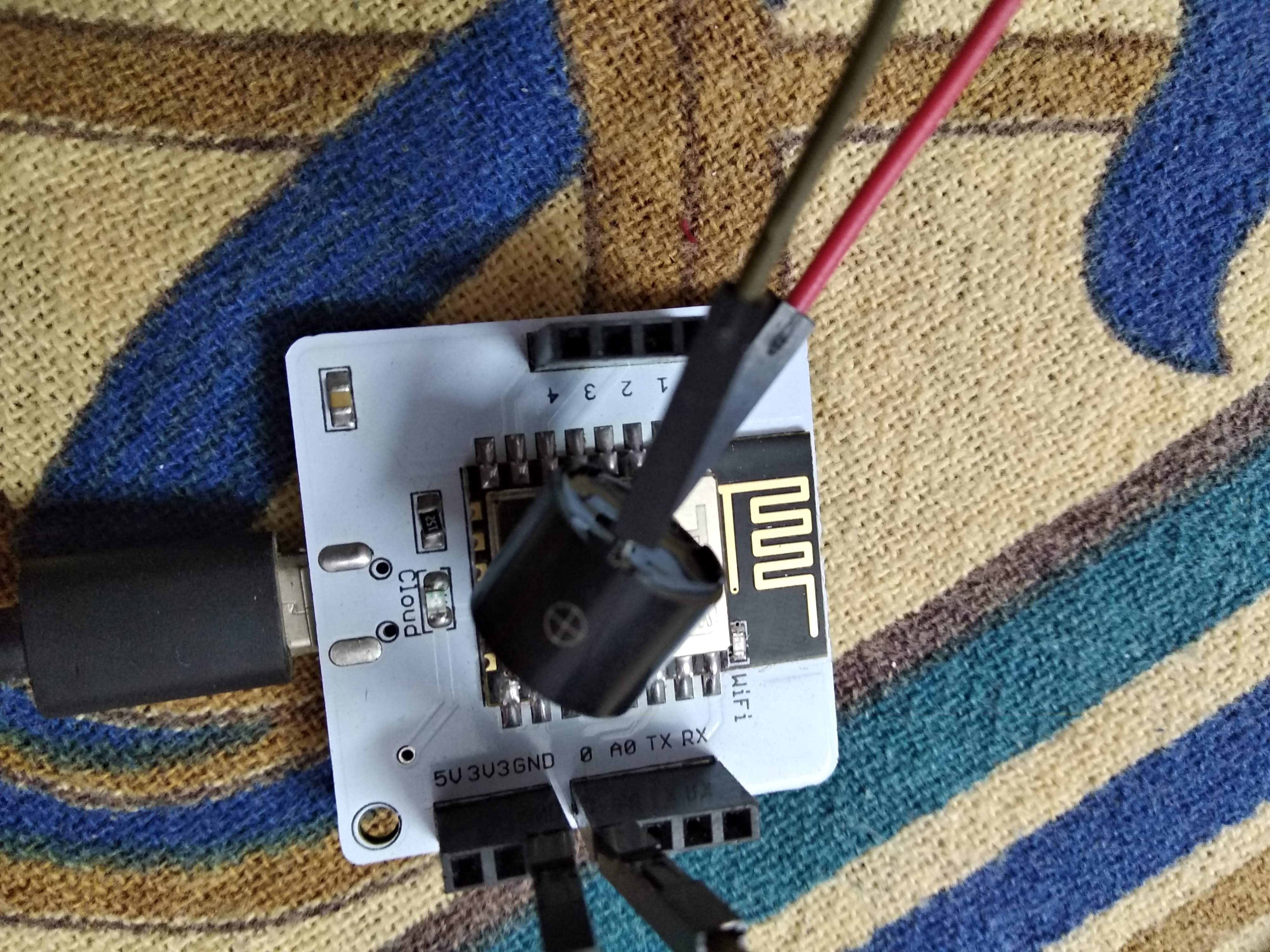
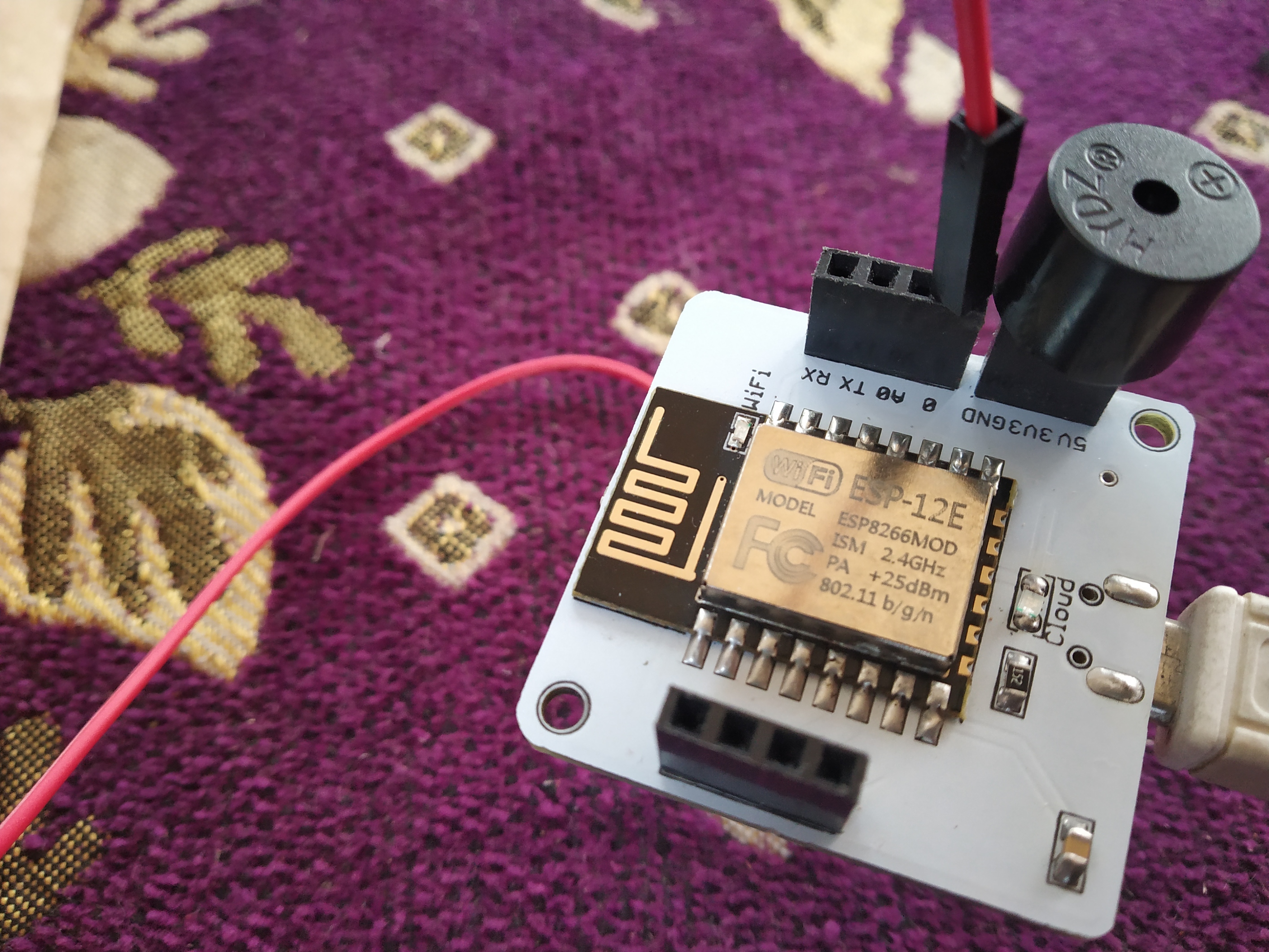
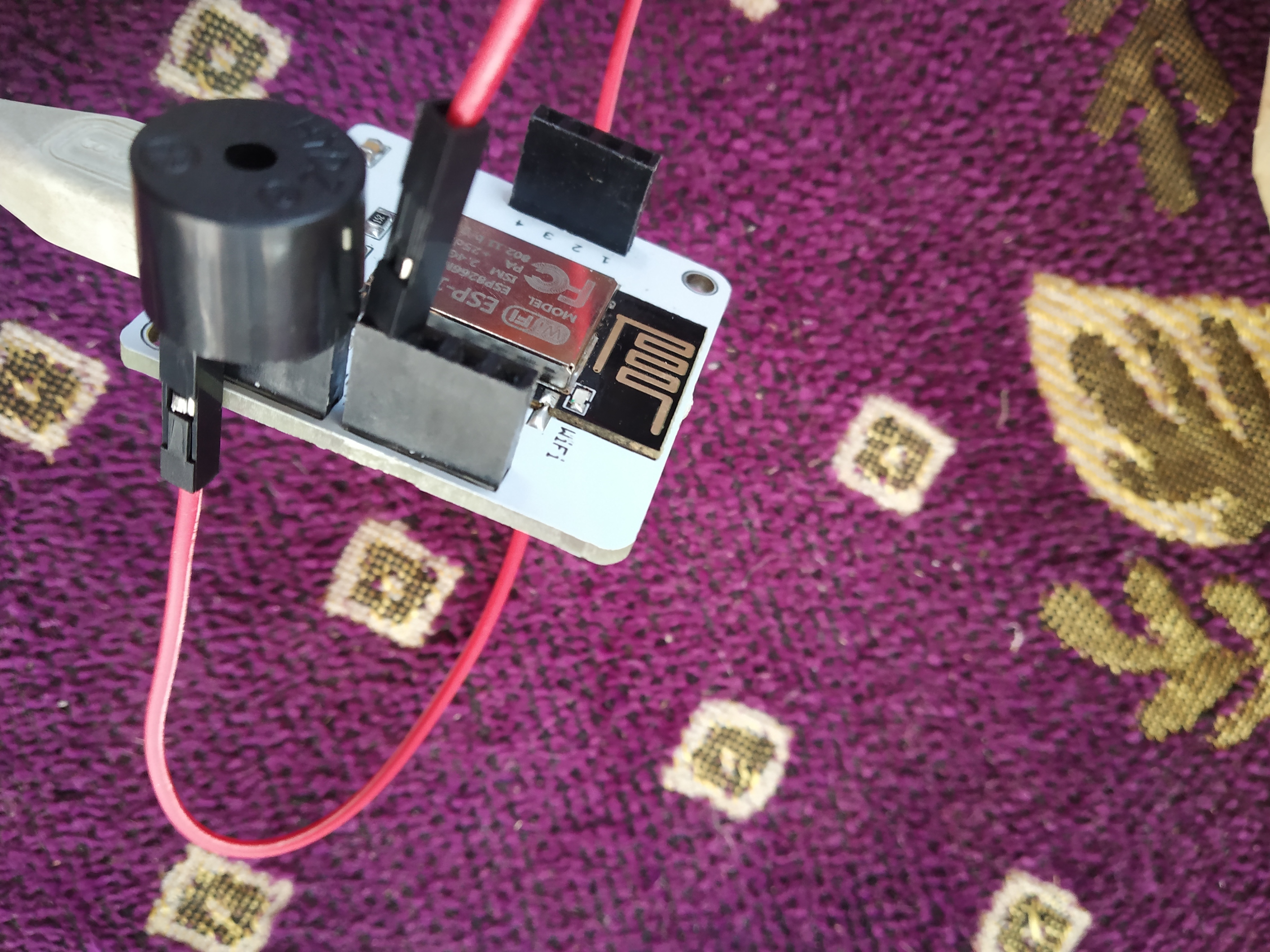
Hey @yashasvi317 ,here’s a picture of connections I made, and it’s working.
It’s similar to LED connection,the longer pin of buzzer should be connected to GPIO pin and shorter one to ground.Don’t use a resistor in this connection. And also remove the seal on the buzzer for clear sound.I hope this helps.
1 Like
Take a male to female wire and fit the male end in A0 pin and female end to the negative side(shorter of two legs) of the buzzer and the positive end of buzzer into the ground(gnd) of the bolt wifi module
What can be the code?
Hey! The code for buzzer remains the same.
So you can use the same code which you used for the led project.
    <!DOCTYPE html>
    <html>
        <head>
            <title>Bolt IoT Platform</title>
            <script type="text/javascript" src="https://cloud.boltiot.com/static/js/boltCommands.js"></script>
            <script>
            setKey('{{ApiKey}}','{{Name}}');
            </script>
        </head>
        <body>

            <button onclick="digitalWrite(0, 'HIGH');">ON</button>
            <button onclick="digitalWrite(0, 'LOW');">OFF</button>

        </body>
    </html>
1 Like
Hi!
I tried the above connection by connecting positive pin of buzzer to A0 pin still for me it doesn’t produce any sound!
Does anyone know what the issue might be?.
It would be a great help.
@rockymad4 The pin should be connected to any digital pin for the buzzer to work. Try connecting it to any digital pin on the board and then set the value as HIGH for that pin.
1 Like
Thank you very much for your response!
There is an API access limit which I was unaware of, that had lead to this issue. As after the limit is reached we cant send signals to it.
Thanks again!
1 Like
If you simply replace led with buzzer, it wont work as mentioned in the video. you have to connect the positive lead of the buzzer directly to the pin 0 of wifi module without connecting 330k ohm to it. I also have done this mistake and later rectified it, do try it…
@jayeshrane999 I had connected the positive pin to Digital Pin 0 and negetive pin to ground and It was working,
But before trying out the buzzer I had been trying out the LED and during that i accessed my API key 20 times in 1 minute which is the limit after that API key is not usable for 6 hours. Because of this limit that i reached I was not getting any response thus leading to no output feedback.
check out this link for API access rules:
It must be inserted in 0 pin for positive terminal of buzzer and negative terminal must be inserted in GND port. There is no requirement of any resistor. But API key must be updated from time to time as there is a policy for limited API access.
1 Like