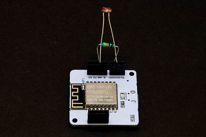
- Step 3: Insert one leg of the 10k Ohm resistor into the GND pin
where should i connect the other leg of Ohm register? i mean to which pin?
We have updated the course content to clear the confusion around the circuit connections.
Below is the connection details for the resistor
Insert one leg of the 10k Ohm resistor into the GND pin.
Insert the other leg of the resistor into the A0 pin.
You can also check the relevant images that we have updated in that lecture.
Hi @roshnidash827
you need to connect the other leg of ohm register into the A0 pin.
You might have confusion that one leg of the LDR is already connected with the A0 pin. Yes, so one leg of the LDR and ohm register are together connected to the A0 pin.
So, there are 2 legs in the A0 pin.
- one leg of the LDR and
- one leg of ohm register
Can you see both legs (1 of LDR and 1 of register) in the A0 pin? That’s how it needs to be connected.
Connect the other leg of resister to A0 pin of bolt module
Connect one leg of 10k ohm resister in to ground and other in to the Ao pin i.e Analog to Digital convertor.
The voltage divider circuit is used here to obtain the voltage between the LDR.
Other leg of ohm register should also plugged into A0 pin.
Hi @roshnidash827
In order for better understanding use breadboard given by the Bolt Iot.
1.Connect 3v3 to a breadboard pin using jumper wire and connect one end of LDR vertically below the junction where you have connected 3v3 to breadboard, Similarly take another jumper wire and connect Analog Output pin from the wifi module to the breadboard. Connect the other lead of LDR vertically below this junction
2. Similarly connect resistor’s one end below the Analog Output junction and other to ground junction
Using Breadboard instead of direct connections in the module will be really useful for other projects in the later part of the course
I have attached a image below


