Boltduino Setup - No Data to Cloud

Hello,

I’ve been trying to build out a couple of basic ideas with my BoltIoT. After my async push question I’ve moved on to using the Boltduino shield. I built a very simple script that uses the PIR to count the number of movements that occur. When movement occurs I light the built in LED. During the loop phase I take the current count and send it via serial. I’ve monitored the serial output to see that everything works as I expect it to. However, I’m not getting any values via the cloud app. It says it never has received a value.

Here’s my script that’s running on the arduino:

#include <BoltIot-Arduino-Helper.h>

int ledPin = LED_BUILTIN;                // choose the pin for the LED
int inputPin = 4;               // choose the input pin (for PIR sensor)
int pirState = LOW;             // we start, assuming no motion detected
int val = 0;                    // variable for reading the pin status
 
void setup() {
  pinMode(ledPin, OUTPUT);      // declare LED as output
  pinMode(inputPin, INPUT);     // declare sensor as input
 
  boltiot.Begin(Serial);

  Serial.begin(9600);
}

int counter = 0;
void loop() {
  // put your main code here, to run repeatedly:

  val = digitalRead(inputPin);  // read input value
  if (val == HIGH) {            // check if the input is HIGH
    digitalWrite(ledPin, HIGH);  // turn LED ON
    if (pirState == LOW) {
      
      Serial.print("Motion detected! Times detected: ");
      Serial.println(counter);
      // We only want to print on the output change, not state
      pirState = HIGH;
      counter++;
    }
  } else {
    digitalWrite(ledPin, LOW); // turn LED OFF
    if (pirState == HIGH){
      // we have just turned of
      Serial.println("Motion ended! ");
      // We only want to print on the output change, not state
      pirState = LOW;
    }
  }

  boltiot.CheckPoll(counter);
}

My cloud app should be very simple as well:

/ *start typing your code here */

setChartLibrary('google-chart');
setChartTitle('Your Graph Title');
setChartType('lineGraph');
setAxisName('X-Axis Name','Y-axis Name');
plotChart('time_stamp','posOne');

The hardware config for the cloud app is for one variable to be read into posOne every 5 min.

Here’s what the serial monitor is output:

Motion detected! Times detected: 130
Motion ended!
Motion detected! Times detected: 131
Motion ended!
132.00,0.00,0.00,0.00,0.00,0.00
132.00,0.00,0.00,0.00,0.00,0.00
132.00,0.00,0.00,0.00,0.00,0.00

The issue is I’m not getting any data. Should I change the 1 value to 6 as it appears to be sending it that when the bolt code fires?

With the bolt on the boltduino it looks as if the tx pin matches up to the tx pin on the board (as it is labeled at the top where I have the bolt plugged in. Is this a misprint or am I actually hooking the bolt up incorrectly?
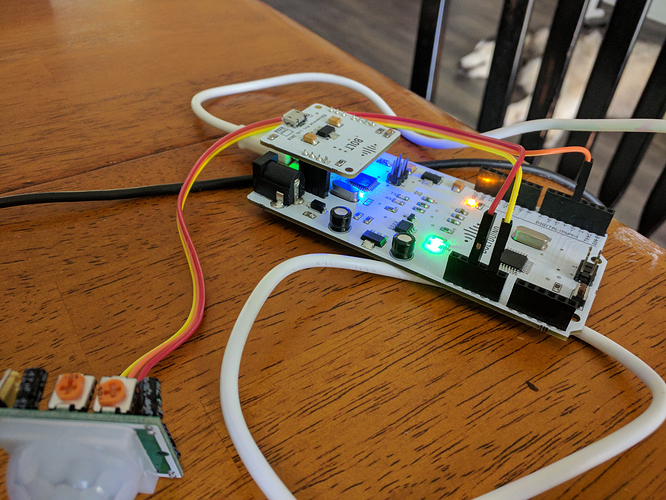
Hi @mikejr83,

For you to push data to the cloud over the UART interface of the Bolt (That’s what you are trying to do), you need to :

  1. Configure the product to which the Bolt is linked to work as UART input.
  2. Write the Arduino code in such a manner that the Arduino continuously reads from the serial port for the “RD\r” command.
  3. When the Arduino receives the “RD\r” command from the Bolt, the Arduino should send the values that you want to log to the Cloud, to the Bolt module.

Writing this code is a cumbersome process and as such we have written a library which reduces your coding effort.

Do try to use it and let us know if it worked for you.

In my original post I outline that I had done that. I’ve since tried setting up the product config to take 1 and 6 values and have not seen any data on the line graph.

I posted the code that is running on the Arduino. I have been using the library. I’ve used the library as it exists from the master branch and from the update-dev branch. Neither of those versions have worked.

I still assume that placing the BoltIoT on the shield in the manner as I’ve shown in my picture is correct. Doing so lines up the TX labeled input on both boards. Is this a misprint on the shield? I have yet to try it, but I will try placing wires from TX to RX and RX to TX to see if that works. To me that seems like it would defeat the purpose of an otherwise nicely designed layout.

Hi @mikejr83,

I had not clearly read your earlier code. If you are using the CheckPoll function, then you have to set 6 CSV in the product configurations. (Doesn’t matter if you use master or update Dev)

What seems to be happening is that you are printing the status of your code on the serial port.

While this is a common practice, the Bolt module stores this as data.

So when it sends an “RD\r” command, it already has “Motion detected!” In its serial input buffer, which it sends to the Bolt Cloud.

The Cloud interprets this as wrong or ill-formed data and discards it.

So when you are using the library, with the Hardware serial port, do not print anything to the serial object and do not scan anything from it either.

If you follow this, your code should give the right result.

Also you have mounted the Bolt module correctly, and there is no miss-print. The tx, rx, a0, 0, 1,2,3,4, 5v, 3.3v and gnd pins of the Bolt are supposed to mate with their counterparts printed on the BoltDuino.

Where can I purcahse the BOLTDUINO module from ?

Hi @nookalaarpan12,

As of now, we are not seeling the Boltduino.
I have added you to the requester’s list for the Boltduino. When we do launch it as a product we will send an email to you as well.

hey can i know where you have got boltduino
reply asap…

I want to get a boltduino , consider me adding to requester list
plz confirm with a reply

I will check with my team and get back to you.

1 Like

@mummanajagadeesh97 You may purchase Boltduino from this link: Pay Rs. 1750.00 to Bolt IoT (@boltIoT) on Instamojo

We generally ship within one working day.