Hello sir i have a doubt regarding connections of ldr circuit
Is it that one lead of ldr should be in A0 pin and other in 3v3
And one leg of 10k resistor in gnd and other leg in A0 pin
Yes, you are right. This way the resistor and the LDR get connected in series. The reading is measured on A0 pin which in turn is the voltage across the LDR converted to bytes internally.
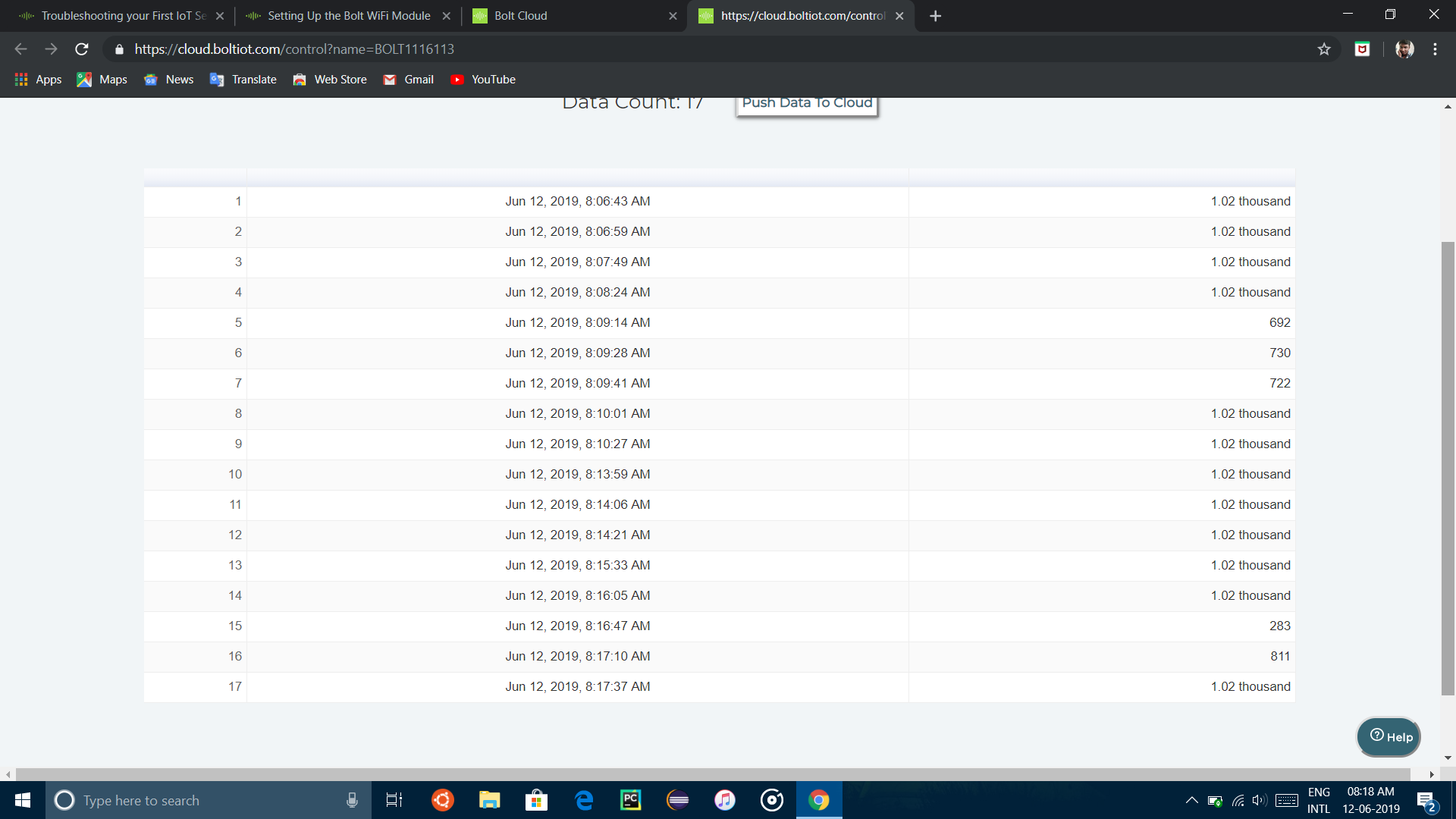
i did the same connection to the bolt module and i got the readings as in the image.when i hide the LDR with my finger then it is showing less value, its fine. but when i put my setup in the sunlight, under torch of my iPhone it is showing 1.02 thousand value constantly even i change the lighting conditions.
It is probably because ldr is an analog sensor of 10 bit value in which the data can fall between 0-1023. The ldr provided might be having a maximum set to 1.02 thousand. Therefore, light falling on the ldr beyond a certain limit is read 1.02 thousand only.
sir please use 330ohm resistor instead of 10k ohm and check the valves.I used 330 ohm and i got valves with in the range.
@Nikhil The range of the LDR sensor with which it can measure the intensity of the light is limited. It will not be able to tell the difference between bright sunlight and low sunlight as sunlight is a powerful source of light.
Therefore, please conduct the experiment indoors under normal lighting conditions and remember to use 330 Ohm resistor.
But Sir, even I faced the same problem as @Nikhil faced.But then I even tried the method you said…i.e) I used 330 ohm resistor,but still I get the same 1.02 thousand values,and if I close the LDR sensor with my finger,the value is changing else it remains constant.
@dhivyaassn It seems that you are giving too intense a light to the LDR.
Try doing the experiment in a dimly lit room.
Sir I got trouble in rebuilding that product. Two days before I build the product it was working properly and was providing me the output, Today it is not working. What to do ?
Yes,you are right that is how you do it.
@deepankarrai99 What error are you facing? Please elaborate and provide any screenshots if required.
Yes you are right
you should also try using 330 ohms resister
it gives some better results


In LDR circuit ,one leg of LDR sensor should be in A0 pin & other in 3v3
The resistor pins in gnd and A0.
But make sure that the 3.3V (or even 5V) and GND pins or wires coming out should NOT touch each other. If you short power to Ground without a resistor, the current drawn might be high enough to destroy the Bolt module.
Make sure you have made the connections properly and also make sure that the bolt module is connected
Remember If the 3.3V (or even 5V) and GND pins or wires coming out of them touch each other. If you short power to Ground without a resistor even accidentally, the current drawn might be high enough to destroy the Bolt module*
Hello sir, I had a small confusion. In the training, under the light monitoring sytem project (Project 1), in the ‘Hardware Connections’ lecture, it is mentioned that “Thus, we are effectively measuring the voltage across the 10k Ohm Resistor and the final circuit should look like the image below”. Why is it mentioned that the voltage across the 10k Ohm resistor is being measured?
Use 330 ohms resistor in your circuit. It should work properly
when i used 10k resistor ,i also got the same values.This is because LDR is not able to differentiate between the varies intensities of light.Thus the maximum value possible 1.02 thousand always gets displayed .try using 330 ohm resistor(orange orange brown gold) for correct results