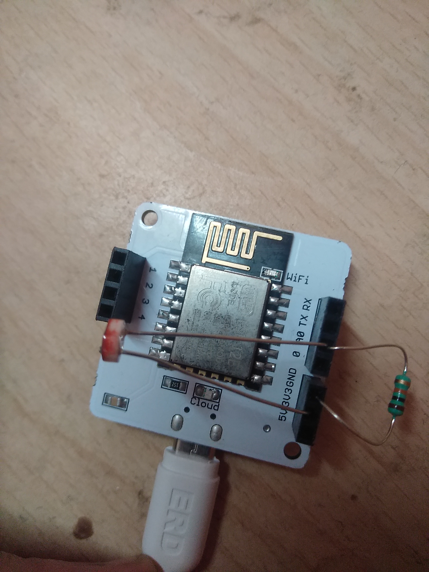
I belive you are building light monitor. Your circuit seems to be fine. Good to go.
Yes,The Circuit which you have built is absolutely correct and as you know you have built a voltage divider circuit ,you have connected the 10k ohm resistor and LDR sensor in series with one pin of resistor to the ground and one pin of LDR sensor to 3.3V and then the left out pins of LDR and resistor are connected in series by putting both into pin ‘A0’ .So , it seems that your connection is well established you can carry out your experiment.
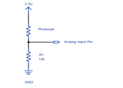
Here the photocell refers to LDR sensor.
In your Analog Input pin is ‘A0’
Here after looking at the image you can get still clarity that you have connected your circuit correctly.
Thankyou so much sir. My Light intensity monitoring system project is running successfully